Calibrating a Low-Pressure Ground Sprayer: Boom-Mounted Nozzles
Calibration is the process of adjusting or modifying spray equipment so it is capable of applying the desired rate of pesticide accurately and uniformly to the target crop area (Figure 1). The performance of any pesticide depends on the proper application of the correct amount on the target area. Most performance complaints about agricultural chemicals can usually be traced back to errors in mixing or applying this chemical. This document will present the best practices for reducing application errors. For mixing refer to PSS-2789, Herbicide Mixing Order.
Variables Affecting Application Rate of Spray Solution
Three variables affect the amount of pesticide mixture or spray solution applied per acre:
- nozzle flow rate.
- ground speed of the sprayer.
- effective spray width per nozzle
To calibrate a sprayer accurately the effect of each of these variables on sprayer output must be understood.
- Nozzle Flow Rate - The flow rate through the nozzle varies with orifice tip size, nozzle pressure and
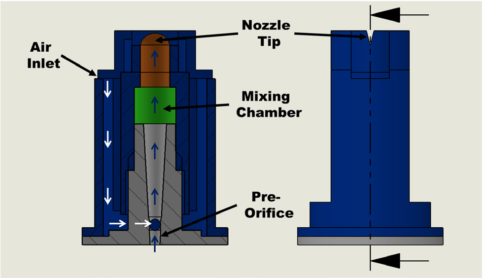
spray solution characteristics. Figure 2 shows a cutaway of a typical low-drift air-induction
nozzle with identifiable parts labeled. The size of the nozzle is determined by the
size of the pre-orifice for low drift nozzles or the main orifice for standard nozzles.
Installing nozzles with a larger or smaller orifice size is the most effective way
to change a sprayer's output.
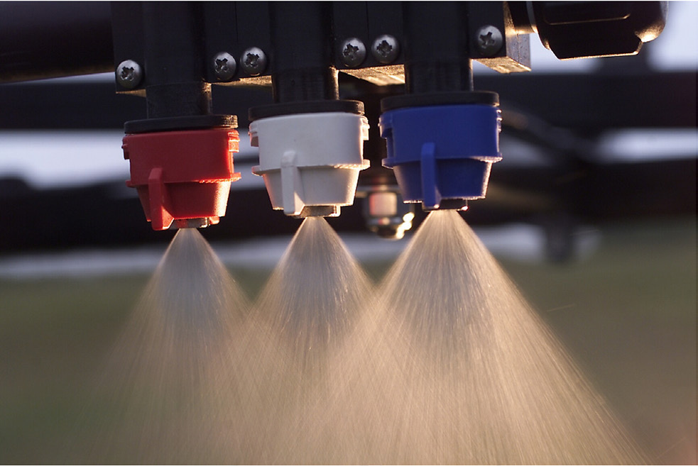
Figure 1. Calibration is the process of adjusting spray equipment to uniformly apply the desired rate of chemical.
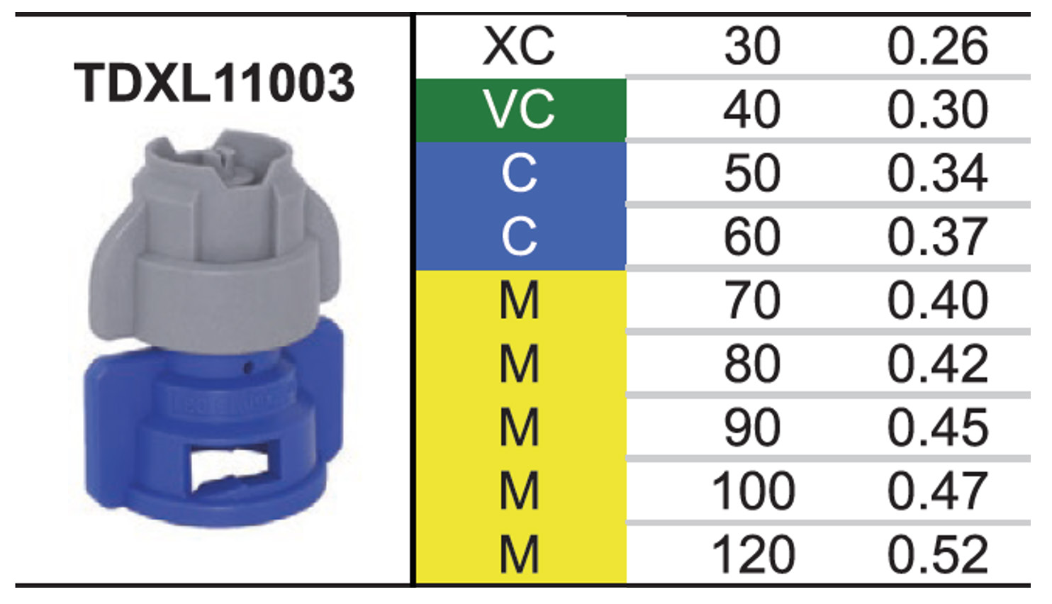
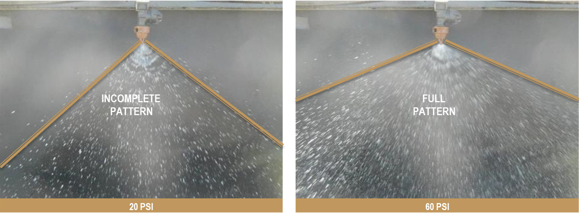
Changes in nozzle pressure also can be used to increase or decrease sprayer output, but not as significantly as changes in orifice size. Pressure must be increased four times to double nozzle flow rate. For example, Figure 3 shows a typical catalog chart for a nozzle. For this particular nozzle, to increase the flow rate of the nozzle from 0.26 gallons per minute (GPM) at 30 pounds per square inch (psi) on the low end of the range to 0.52 GPM, pressure would need ot be increased to 120 psi (4 x 30). Pressure adjustment should never be used to make major changes. Most nozzles have an optimal working pressure somewhere near the middle of the manufacturer suggested range. Pressures near the low end of the range may distort the spray patter (Figure 4), while pressures near the upper end of the range tend to produce small droplets and increase physical spray drift. The pressure range of nozzles vary greatly from model to model but can vary from as low as 15 psi to upwards of 120 psi.
Figure 2. Cut away model of a TeeJet AIXR nozzle. White arrows show airflow and blue arrows show liquid flow. - Ground Speed - The spray solution application rate varies inversely with the ground speed. Doubling
the ground speed of a sprayer reduced the gallons of spray applied per acre (GPA)
by one-half. For example, a sprayer applying 20 GPA at 3 mph would apply only 10 GPA
at a speed of 6 mph if all other spray conditions remained the same. A sprayer calibrated
at 4 mph but actually operated at 3 mph will over spray by 33%, significantly increasing
chemical costs and the potential for crop damage.
Figure 3. Excerpt from GreenLeaf Technologies Catalog for a TurboDrop® XL nozzle. - Effective Spray Width "W" - The effective width sprayed per nozzle or cluster of nozzles also affects the spray solution application rate. Spray width per nozzle is measured differently depending on the nozzle configuration. Refer to Figure 5 for the best way to measure effective width. Doubling the effective spray width will decrease the gallons per acre (GPA) applied by one-half. For example, if a broadcast nozzle is applying 40 GPA on a 20-inch spacing, a change to a 40-inch spacing will decrease the application rate of spray solution to 20 GPA. Typically, this will require changing the nozzles to a wider fan angle or increasing boom height to maintain proper overlap. Both of these changes can have impacts on drift.
Precalibration Checks
Before calibrating a sprayer, service the entire unit. Check that all nozzles are the same size and not worn. Check for uniform nozzle output and pattern and determine exactly how much liquid the sprayer tank holds. Install a pressure gauge on the boom to determine actual pressure at the nozzles.
Servicing - Clean all lines and strainers, making sure the strainers are in good condition and the correct size and type for the chemical formulation to be applied. Inspect all hoses for signs of aging, damage and corroded fittings or leaks. Check the pressure gauge to determine if it is working properly. Is the pressure holding constant? Does it read zero when the pump or boom valve is shut off? The actual accuracy of the gauge is not as important as its ability to give the same reading each time the same pressure is produced. At least once a year, preferably at the beginning of the spraying season, check the gauge against another gauge known to be accurate.
Nozzle Output and Pattern - Check for uniformity of nozzle output and the spray angles, spacing and height are consistent. To check for uniform nozzle output, install the selected nozzle tips and check to be sure the tank is clean. Then partially fill the tank with clean water and operate the sprayer at a pressure within the recommended range. Place a container, such as a quart jar, under each nozzle and check to see whether all the jars fill at about the same time (Figure 6). Replace any nozzle tips with an output that significantly varies compared to the output of the rest of the tips, have an obviously different fan angle or have a non-uniform appearance in spray pattern. The rule of thumb is nozzles with flow rates greater than 10% above a new nozzle of identical make should be replaced.
An effective way to determine whether a uniform pattern in being produced and whether the boom is at the proper height is to spray some water on a warm, dry, light-colored surface like a concrete pad or gravel drive and observe the drying pattern. If the pattern is not uniform, some strips will dry slower than others will.
Figure 4. Improper pattern development (left) vs proper pattern (right).
Tank Capacity - Checking tank capacity may seem unnecessary, but unless the exact capacity of the sprayer's tank is known, it may lead to serious problems. This precalibration check should be made at least once, and the data should be recorded. When determining application rates of spray solution, the use of an inaccurate tank capacity is a common cause of many cases of under- and over-application. A tank thought to hold 200 gallons, but which actually holds 250 gallons, results in a built-in calibration error of 25%. The best and easiest way to accurately determine tank capacity is to fill the tank using any convenient container for which an exact capacity is known. Another effective way of measuring tank capacity is to fill or drain the tank while measuring with an accurate flow meter.
A third way is to weight the sprayer both empty and full. The difference between the two weights is the weight of the water in the tank. The capacity of the tank in gallons can then be determined by dividing this weight by 8.33 pounds, which is the weight of one gallon of water.
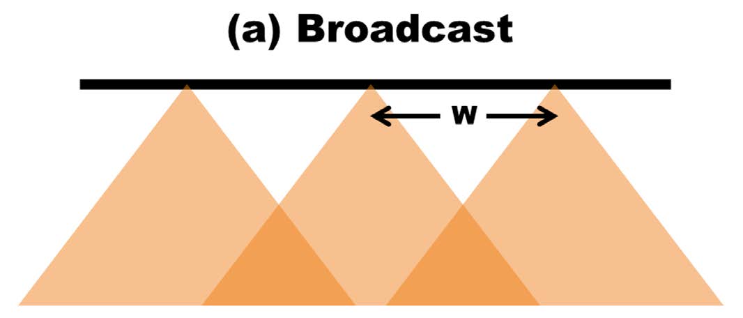
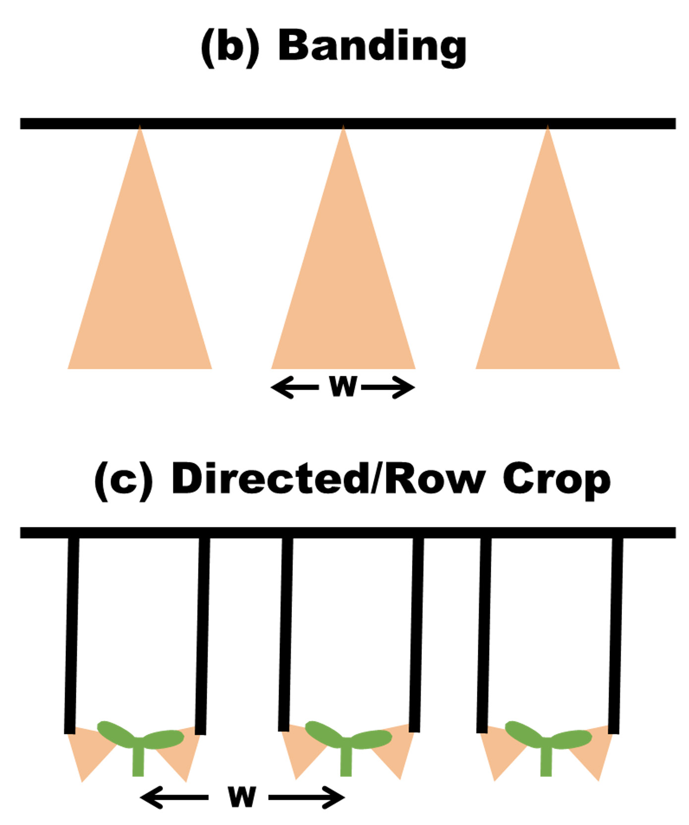
Figure 5. Effective Width Calculation - (a) for broadcast applicators measure the distance between adjacent nozzles, (b) for banded applications measure the wetted width of the band and (c) for directed or row crop applicators measure th erow spacing and divide by the number of nozzles per row.
Measuring Ground Speed
To apply pesticides accurately, a constant ground speed must be maintained. Field conditions, such as surface roughness, softness and slopes, all affect ground speed due to wheel slip and this can significantly change application rates of spray solution. Tractor speedometers and tachometers are generally not a good means of determining ground speed because wheel slippage can result in speedometer reading errors of 25% or more. Changes in tire size also can affect speedometer readings. The best way to accurately measure ground speed is with a true ground speedometer that utilizes a radar, GPS guidance system or other speed measurement device. GPS guidance systems are the most common way to determine true ground speed in most situations, but many of the sprayer monitors and rate controllers currently on the market have the ability to accurately measure true ground speed using radar or other devices. These speedometers are available from a number of spray-equipment manufacturers at reasonable prices and are a good investment if a considerable amount of spraying is done.
If a true ground speedometer is not available, the next best method to assure a constant ground speed is to measure the speed of the sprayer at a variety of throttle and gear settings. Do this in the field to be sprayed or a field that has conditions and terrain similar to those in the field to be sprayed. To measure true ground speed, stake out a known distance in the field. Suggested distances are 100 feet for speeds up to 5 mph, 200 feet for speeds from 5 to 10 mph, and at least 300 feet for speeds above 10 mph. At the engine throttle setting and gear to be used during spraying, determine the travel time between the measured stakes in each direction. To ensure the greatest accuracy, the sprayer should be at least half full of liquid. Average the two travel times and use the following equation or Table 1 to determine the ground speed.
(1) Speed (mph) = D X 60/T X 88
D = the distance between the two stakes in feet.
T = average time in seconds it takes to drive between the stakes.

Table 1. Time to travel distance (seconds).
| Ground Speed | (mph) | ||||||||||
|---|---|---|---|---|---|---|---|---|---|---|---|
| Distance (ft) | 3 | 4 | 5 | 6 | 7 | 8 | 9 | 10 | 12 | 15 | 20 |
| 100 | 23 | 17 | 14 | 11 | |||||||
| 200 | 45 | 34 | 27 | 23 | 19 | 17 | 15 | 14 | |||
| 300 | 68 | 51 | 41 | 34 | 29 | 14 | 23 | 20 | 17 | 14 | 10 |
The numbers 66 and 88 are used because 1 mph = 88 feed in 60 seconds.
Calibration Methods
The actual calibration of a field sprayer involves two important steps:
- Step 1. Determine whether the sprayer is applying the correct number of gallons per acre (GPA) of pesticide mixture set by the label.
- Step 2. Using the GPA from Step 1, determine how much pesticide should be added to the sprayer’s tank to achieve the desired application rate of spray solution.
The focus will be determining the sprayer output (Step 1) and making any equipment adjustments necessary to ensure the proper application rate in gallons per acre (GPA). There are many different methods to determine this flow rate and two of those will be discussed in the following sections.
NOTE: Sprayer calibration and nozzle testing is done using only water in the sprayer tank. For most water-based spray solutions, the addition of chemicals does very little to affect nozzle flow rates. When using liquid fertilizer solutions as the carrier liquid for chemicals, the nozzle flow rate can vary greatly at higher flow rates. Refer to BAE-1293, Using Water to Calibrate Sprayers for Fertilizers and Other Liquid Solutions for more information on calibrating for other liquid carriers.
Determining Sprayer Output with the Nozzle Output Method
One of the easiest and most effective methods to determine whether the sprayer is actually delivering the rate of spray solution (GPA) desired is the nozzle output method. An advantage of this method is it can be completed with the sprayer stationary and does not require the sprayer be driven in the field. One limitation is ground-driven sprayers cannot be calibrated by this method. In order to use this method, three pieces of information must be known:
- Operating Pressure – will vary by manufacturer but can range from 15 psi to 120 psi, depending on the type of nozzle used.
- Ground Speed – speed normally ranges from 3 mph to 8 mph for pull-type farm sprayers, 5 mph to 12 mph for most self-propelled farm sprayers, and 10 mph to 20 mph for commercial truck-mounted or floater-type sprayers.
- Effective Spray Width “W” – varies with the type of nozzle arrangement used, but 15 inches, 20 inches and 30 inches are common.
Step 1. Fill the spray tank partially with water and operate the sprayer at the selected pressure. Use a container marked in fluid ounces to collect the output of a nozzle for one minute or some convenient fraction of a minute. Make sure all nozzles are spraying uniformly and determine the average number of fluid ounces per minute (OPM) of output for each nozzle.
Step 2. Convert OPM determined in Step 1 to GPM by dividing OPM by 128 (Equation 2).
Step 3. Select the ground speed (mph) at which the sprayer is to be operated. This speed will normally be in the 3 mph to 8 mph range for tractor-mounted or pull-type sprayers, 5 mph to 12 mph for self-propelled farm sprayers and 10 mph to 20 mph for truck-mounted floatation sprayers, depending upon field conditions.
Step 4. Determine the effective spray width (W) in inches. For broadcast spraying, “W” will equal the distance between adjacent nozzles. For banded spraying, “W” will equal the banding width. For row crop spraying with two or more nozzles per row or band, “W” will equal row spacing or banding width divided by the number of nozzles per row or band. See Figure 5 for examples.
Step 5. Once these values are known, the sprayer’s output in gallons per acre can be calculated using the following equations:
(2) GPM = OPM/128
(3) Speed (mph) = GPM X 5,940/MPH X W
GPA = the sprayer’s output in gallons per acre.
GPM = the nozzle output determined in Step 2 in gallons per minute.
5940 = a constant used to convert inches, gallons per minute and miles per hour to
gallons per acre. Alternatively, using 6,000 instead makes the computation easier
and results in an error less than 1%.
MPH = the ground speed selected in Step 3 in miles per hour.
W = the spray width per nozzle which was determined in Step 4 in inches.
128 = the number of fluid ounces per gallon.
For example, a pull-type field sprayer is set up to broadcast spray a herbicide with regular flat fan nozzles spaced 20 inches on center. A ground speed of 5 mph has been selected. The average collected nozzle output is 54 OPM.
What is the application rate of spray solution in gallons per acre?
Using Equation (2).
GPM = 54/128 = 0.4219 gallons per minute
Using Equation (3).
GPA = 0.4219 X 5,940/5 X 20 = 25.06 gallons per acre
With this set of conditions, the sprayer will apply 25 gallons per acre. If this is not the application rate of spray solution desired, then one or more conditions will need to be changed. A small nozzle flow rate change can generally be accomplished by either raising or lowering the pressure within the pressure limitations of the nozzle. A larger flow rate change can be accomplished by either changing the ground speed or by switching to larger or smaller nozzle tips. If 20 GPA was the desired application rate of spray solution, a change in ground speed of
25 GPA/20 GPA = X 5.0 MPH = 6.25 MPH
would provide the desired 20 GPA without nozzle or pressure changes. From Table 1, this would require that a ground distance of 200 feet be covered in 22 seconds.
Determining Sprayer Output with the 1/128th Acre Method
In certain cases, nozzle choices may be limited or there is a desire to know what the current application rate of spray solution (GPA) is for a particular sprayer setup. The 1/128th acre method works well in these instances and allows for a simple determination of application rate of spray solution (GPA) with very few hand calculations required. Typically, this method is used for sprayer setups that do not have an accurate true ground speedometer. In order to use this method, three pieces of information must be known:
- Effective Spray Width “W” – varies with the type of nozzle arrangement used, but 15 inches, 20 inches and 30 inches are common.
- Operating Gear and Throttle Setting – the transmission gear and engine throttle (rpm) must be selected.
- Calibration Area – an area of the field or similar terrain must be available to measure driving times for the sprayer during calibration.
Step 1. Fill the sprayer tank at least half-full of water. Choose the proper driving gear and engine throttle position for proper tank agitation and comfortable forward travel speed. Choose a pressure in the center of the nozzle’s recommended range that produces a good pattern.
Step 2. Determine the Calibration Driving Distance (Table 2) based upon the effective spray width (W) for the sprayer nozzle arrangement. Measure and mark this distance in the calibration area.
Step 3. Measure the time required by the sprayer to cover the distance laid out in Step 2. Repeat this process at least two more times and calculate the average time in seconds for all three passes.
Step 4. With the sprayer stationary and operating at the engine throttle and pressure set during Step 1, use a container marked in fluid ounces to collect the output of one nozzle for the number of seconds calculated in Step 3. Make sure all nozzles are spraying uniformly and the number of fluid ounces of output are similar for each nozzle. The application rate of spray solution in gallons per acre (GPA) will be the same and the number of fluid ounces collected during this step (e.g. 15 fluid ounces collected from each nozzle equals 15 GPA for the sprayer).
Table 2. Calibration distance (feet).
| Spray Width "W" (inches) | Calibration Distance (feet) | |
|---|---|---|
| 8 | 510 | |
| 9 | 454 | |
| 10 | 408 | |
| 11 | 371 | |
| 12 | 340 | |
| 13 | 314 | |
| 14 | 292 | |
| 15 | 272 | |
| 16 | 255 | |
| 17 | 240 | |
| 18 | 227 | |
| 19 | 215 | |
| 20 | 204 | |
| 21 | 194 | |
| 22 | 186 | |
| 23 | 178 | |
| 24 | 170 | |
| 25 | 163 | |
| 26 | 157 | |
| 27 | 151 | |
| 28 | 146 | |
| 29 | 141 | |
| 30 | 136 | |
| 31 | 132 | |
| 32 | 128 | |
| 33 | 124 | |
| 34 | 120 | |
| 35 | 117 | |
| 36 | 113 | |
| 37 | 110 | |
| 38 | 107 | |
| 39 | 105 | |
| 40 | 102 |
Step 5. Adjust pressure to make minor rate changes and repeat Step 4. Otherwise, select a new gear and/or throttle position and start back at Step 1.
For example, a pull-type field sprayer is set up to broadcast spray a herbicide with regular flat fan nozzles spaced 20 inches on center. A gear of A4 and throttle of 2,200 rpm has been selected. A pressure of 40 psi has been set. An open field with similar terrain to pasture that will be sprayed has been selected for calibration.
What is the application rate of spray solution in gallons per acre?
Using Table 2, a nozzle spacing of 20 inches along the boom for a broadcast sprayer requires a calibration distance of 204 feet. This distance is laid out over the calibration area. After three passes, the average time required to cover 204 feet is 31 seconds.
Water is then collected from one nozzle for 31 seconds resulting in 19 fluid ounces in the measuring jar. The sprayer will be applying 19 gallons of spray solution per acre covered. Water also is collected from every other nozzle on the boom. Any nozzles that vary greatly from 19 fluid ounces should be replaced.

