Vibration Table for Food Processing
Introduction
Numerous foods require deaeration that can be accomplished by vibration. Examples are cake batters, chocolate bars, hard candy, jams and liquids that retain air bubbles. Vibration can be used to assist with leveling viscous batters. Vibration may also be used to help with the removal of products from molds. Finally, vibration can be used to settle particulates and reduce packaging size requirements. The purpose of this fact sheet is to describe an example of a low-cost, effective, and easy-to-fabricate vibration table for food and agricultural products. Figure 1 shows a completed vibration table. Products are placed on the table surface for vibration treatment (see Figure 13). The system requires a standard 120V AC electrical connection to operate, is simple and rugged. Construction time (not including adhesive drying) is under 4 hours.
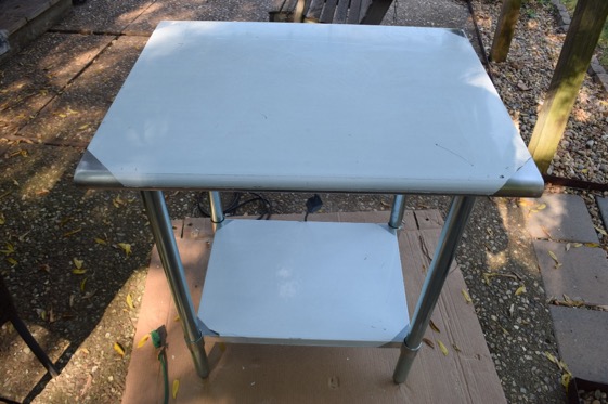
Figure 1. Prototype of a low-cost vibration table.
Components
Major components of a prototype vibration table are listed in Table 1, along with their description, cost and source. Component substitutions are encouraged. Alternative tables, vibration motors, adhesives, attachment means and accessories are widely available. Merit of substitutions should be evaluated for each application. For example, cleanup and maintenance issues may surface with use of some material and component alternatives.
Table 1. Components and accessories for prototype vibration table.
| # | Description | Qty | Cost each* | Cost | Source and Image | |
|---|---|---|---|---|---|---|
| 1 | Stainless Prep Table 24x30”, NSF, Heavy Duty; PN HSW-2430E, Ean 0713929541362 | 1 | $123.49 | $123.49 | Amazon |  |
| 2 | TOAUTO Concrete vibrator motor, 30W, 1 phase, 110V, 3,600 rpm | 1 | $49.00 | $49.00 | Amazon | |
| 3 | MDF Wood scrap, about 30x15x3/4”, cut to fit | 1 | NA | NA | Shop scrap | |
| 4 | Plywood scrap, about 20x15x3/4”, cut to fit | 1 | NA | NA | Shop scrap | |
| 5 | Liquid Nails adhesive, Extreme Heavy Duty, 10 ounce tube | 2 | $3.98 | $7.96 | Local hardware store |  |
| 6 | Loctite thread locker RED 271, 0.28 fluid ounce tube | 1 | $6.98 | $6.98 | Local hardware store |  |
| 7 | M&R Industry RZX 13” rivet nut tool, PN 4354324757 | 1 | $29.98 | $29.98 | Amazon | 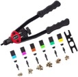 |
| 8 | 1/4”-20 x 1-1/2” Phillips head machine screws | 2 | $1.28 (3-pack) | $2.56 | Local hardware store | |
| 9 | ¼”-20 x 2-1/2 Phillips head machine screws | 2 | $1.28 (2-pack) | $2.56 | Local hardware store | |
| 10 | ¼-20 Nylon Insert Lock Nuts | 1 | $2.28 (6-pack) | $2.28 | Local hardware store | |
| 11 | 1/4x1” Fender washer | 1 | $2.28 (6-pack) | $2.28 | Local hardware store |  |
| 12 | Cdmall Electronic Fan Speed Controller**, 120V, 12A, PN B07T9BLj7L | 1 | $17.99 | $17.99 | Amazon |  |
| 13 | Drill bit, 21/64” | 1 | $4.68 | $4.68 | Local hardware store | |
| 14 | Silicone anti-skid mat** 24x16 (PN TX-180317) | 1 | $11.94 | $11.94 | Amazon | |
| 15 | Conical compression springs (PN 1692K77) | 4 | $12.14 | $48.56 | McMaster-Carr | |
| 16 | Neodymium rectangular magnets** (8-pack, PN NI60-8, Ean 7267232309438) | 1 | $19.79 | $19.79 | Amazon | |
| 17 | Plastic cutting board**, 1/4" thick | 1 | $4.49 | $4.49 | Amazon | |
| 18 | 2-1/4" arbored hole saw** | 1 | $14.48 | $14.48 | Local hardware store | |
| 19 | 1/4 x 1-1/4" Concrete anchors** (8-pack) | 1 | $3.48 | $3.48 | Local hardware store | |
| 20 | 3/16" x 3-1/2" Masonry drill bit** | 1 | $5.98 | $5.98 | Local hardware store | |
| TOTAL | $358.48 |
* tax and shipping not included
** optional item
Assembly
A vibration motor (Table 1, item 2) can be installed on a convenient support structure that has good contact with the underside of the tabletop. The prototype (shown in Figure 1) makes use of a new, stainless-steel utility table (Table 1, item 1), the type that is commonly used in the food and restaurant industry. Important issues to address for the table include:
- Structural support for the vibrator
- Strength to withstand vibration
- Open design with smooth surfaces for cleaning and sanitizing
- Relatively low cost
The table purchased for the prototype vibrator had two support channels that were glued/screwed to the underside of the tabletop (see figure 2). Support channels are a common element for this type of table. The channels provide stiffness for the tabletop and strength to support the leg attachment sockets. The vibrator motor was attached to a wooden “support board” that was in turn attached to the underside of the table. It was decided to screw and glue the support board across the channels of the table. The gap between the support board and the underside of the tabletop was be filled with a “sandwich board”, glued in place between the underside of the tabletop and the support board. Installation of the vibration motor and the sandwich and support boards is described below.
General shop tools and supplies needed for the project are listed below. Less common tools and supplies needed are specified in Table 1.
Tools:
Marking pen/pencil, drill, 1” spade bit, 1/8” drill bit (for pilot holes), spatula, saw horses or worktable, ruler/straight edge, screwdriver, wrenches for tightening nuts, caulk gun, extension cord.
Supplies:
Gloves, rags, safety glasses, sandpaper, scrap boards, solvent (for cleaning).
A scrap of medium-density fiberboard (MDF), ¾” thick, was cut to form the sandwich board, and sized to fit between the channels as shown in Figure 2. When placed between the support channels, the surface of the MDF sandwich board was nearly flush with the surface of the channels. [Note: almost any board will work for this application if its thickness is nearly the same as the height of the support channels.]
A scrap of ¾” plywood was sized to form the support board that bridged the two channels as shown in Figure 3. [Note: The support board must be solid, unlikely to split, and strong enough to support the vibration motor]. Three rivnuts (1/4x20) were inserted into each of the channels (Figure 4) to receive screws that secured the plywood support board to the channels. A rivnut kit (Table 1, item 7) came complete with a rivnut insertion tool and an adequate supply of various sizes of rivnuts for the project. Figure 4 shows placement of the rivnuts in the channels. Location of the rivnuts was determined by drilling six pilot holes for the rivnut screws through the support board. The support board was placed across the channels, fixed in place, and a drill was use mark the channel at each pilot hole location.
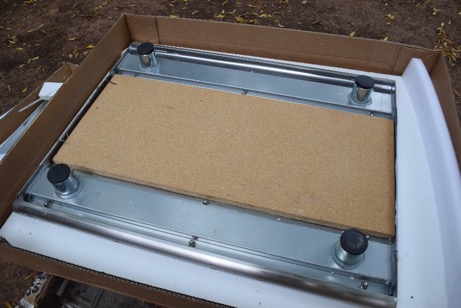
Figure 2. Underside of stainless steel tabletop, showing the two support channels and the MDF sandwich board that was cut to fit between the channels.
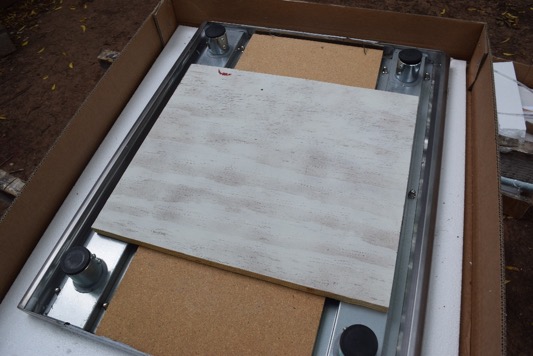
Figure 3. A ¾” thick plywood scrap was cut to form the support board. The support board was sized to bridge the channels located on the underside of the tabletop.
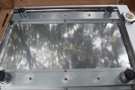
Figure 4. Shows placement of six, ¼-20 rivnuts in the support channels of the underside of
the table. The rivnuts were used to mount the support board.
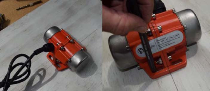
Figure 5. Placement of vibration motor at the center of the face of the plywood support board.
The sandwich and support boards were set in place and the support board was loosely attached with the ¼-20 screws to two of the rivnuts to locate the position of the vibration motor as shown in figure 5.
After the motor position was located and marked at approximately the center of the face of the support board, pilot holes were drilled through the plywood support board and into the surface of the MDF sandwich board. After drilling pilot holes, both boards were separated from the stainless table and the pilot holes were drilled to size for the four vibration motor mounting screws (Table 1, item 9) and washers (Table 1, item 11). The face of the MDF sandwich board contiguous to the underside of the tabletop was countersunk using a spade bit to recess the screw heads and washers as shown in Figure 6. The heads of the screws needed to be at, or lower, than the surface level of the MDF board to insure good contact between the MDF board and the underside of the tabletop.
Next, the contact surfaces of the table and boards were prepped and cleaned for gluing the sandwich and support boards. Coarse sandpaper was used to roughen the surface of the stainless steel table and channels to improve glue adhesion. A clean rag was wetted with solvent to wipe grime and oil from surfaces to be glued.
Adhesive (Table 1, item 5) was applied to the MDF sandwich board surface (tabletop contact side) and spread into a generous layer with a spatula as shown in Figure 7. The MDF sandwich board was placed onto the underside of the tabletop. When setting the sandwich board, take care to retain the mounting screws and washers for the vibration motor in place. Next, the exposed side of the sandwich board, along with the support channels of the underside of the tabletop, were covered with a generous layer of adhesive (see Figure 8) to attach the support board.
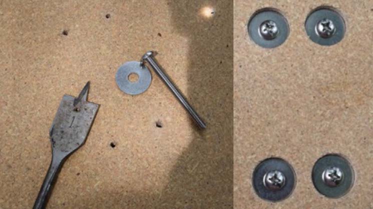
Figure 6. This figure shows two photos of the face of the MDF sandwich board that will be glued to the underside of the tabletop. The photo on the left includes a 1” spade drill bit that was used to countersink the MDF surface at each pilot hole for the vibration motor mount screws (orange arrow indicates one of the four pilot holes) to recess the washers and screw heads. Photo on the right shows the washers and screws inserted into the board after countersinking and drilling the pilot holes to full size. [Note: countersink the pilot holes before drilling holes to full size to prevent centering issues with the spade bit.]
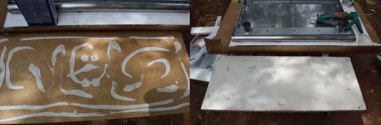
Figure 7. Adhesive spread on MDF sandwich board. Left shows globs of adhesive, and right photo shows the adhesive spread into a film. Note that the screw heads and washers for mounting the vibration motor were completely covered with adhesive
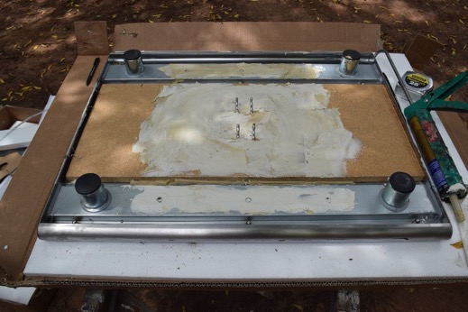
Figure 8. Adhesive was spread on the MDF sandwich board and tabletop support channels after the MDF board was set in place. Note the four mounting screws for the vibrator motor extend from the surface of the MDF sandwich board (orange arrow indicates one of the mounting screws).
Next, the plywood support board was positioned over the MDF sandwich board and channels and attached to the channels using six, ¼-20 x 1.5” screws (Table 1, item 8) threaded into the rivnuts. Temporary ¼” nuts and washers (not included in Table 1) were installed on the vibrator mounting screws (see Figure 9) to hold them in place and to help achieve contact between the two boards. Weights (in this case, containers filled with water) were stacked on the table (Figure 10) to improve contact of the surfaces being glued. The adhesive was allowed to dry for 3 days.
After the construction adhesive was fully dried, exposed wood surfaces on the underside
of the tabletop were sealed with a waterproof paint. Next, the table was assembled
according to the manufacturer’s instructions. Threaded fasteners were treated with
a permanent thread locker compound (Table 1, item 6) to prevent loosening due to vibration.
The vibration motor was mounted using the four screws as shown in Figures 9 and 11,
and held in place using nuts with integral nylon lock-washers (Table 1, item 10).
The completed table, still covered in protective film, is shown upright in
Figure 1.
Installation and Startup
Operation of the table requires a stable support surface for the legs. Almost any floor surface in a typical food manufacturing facility will work. The table should be supported in a manner that will not dampen vibration. Conical compressions springs (Table 1, item 15) may be placed under each leg of the table to reduce effects of vibration on the floor.
An alternative to anchoring the springs to the floor is to use plastic or metal disks or washers. The discs, sized to fit inside the larger opening of the conical spring (2.25”), can be fixed to the floor. The disks will prevent the conical springs from moving horizontally. For the prototype application, a hole saw (Table 1, item 18) was used to cut four disks from an inexpensive plastic cutting board (Table 1, item 17). The disks were screwed to the floor using concrete anchors (Table 1, item 19). Holes for the anchors were drilled using a masonry bit (Table 1, item 20).
An electrical connection rated at 120VAC, that can support 40 Watts (about 1/3 amp), is needed for the vibration motor. The vibration motor may require adjustment. Vibration frequency can be adjusted using the variable speed control (Table 1, item 12). The amplitude of the vibration may be adjusted by moving the weights attached to the shaft of the vibration motor. The procedure for amplitude adjustment is described in the literature that comes with the vibration motor. Note that amplitude adjustment may also affect frequency.
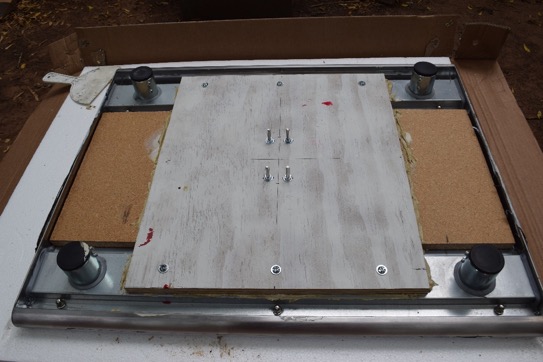
Figure 9. Plywood support board glued and screwed to the underside of the tabletop and the MDF sandwich board. Note the four mounting screws for the vibration motor (one screw indicated by an orange arrow), tightened in place with temporary nuts and washers.
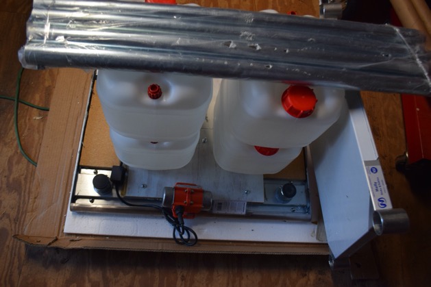
Figure 10. Weights (water-filled containers and table legs) were stacked on the plywood support board to help promote glue and surface contact. Water mass was about 44 kg.
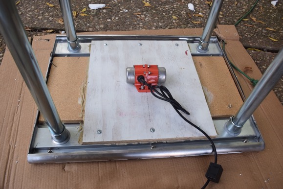
Figure 11. Vibration motor mounted on the support board.
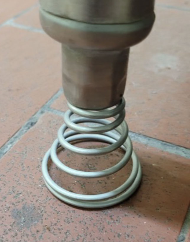
Figure 12. Conical spring supporting table leg. In this example, the spring is fixed to the bottom of the table leg and has not been secured to the floor.
Operation
Food products requiring vibration processing can be placed on the surface of the table for as long as needed (Figure 13). If the products “walk” off the table, a thin, anti-skid, silicone mat (Table 1, item 14) can be added to help keep them in place. Another option is to build and install a border frame attached to the tabletop with magnets (magnets shown in Table 1, item 16). The border frame can be made from PCV trim board that is available at local hardware stores (not included in Table 1).
To reduce wear of the table and components, the vibrator motor should be operated only when the table is in use. A foot switch (not included in Table 1), or the switch on the speed control (Table 1, item 12), or removing the plug from the power outlet, can be used to toggle the vibration motor on and off.
Cleaning
The tabletop should be washed with a clean cloth dipped in a solution of warm water and dish soap, followed by rinsing. After rinsing, dry with a squeegee and sanitize with a food-safe disinfectant such as quaternary ammonium or alcohol according to product instructions. The underside of the tabletop includes wood and electronic components and should not be sprayed or flooded with water during cleaning. Dry cleaning techniques, such as vacuuming and wiping with antiseptic cloths, are appropriate for the underside of the tabletop.
Safety
Safety features are important to protect operators and other personnel from injury. The vibrator motor is electrically energized and should be unplugged prior to any maintenance and cleaning activities on the table or its components. Do not allow the vibration motor to be soaked or sprayed with water. The vibration table should be routinely inspected for safety (e.g. general appearance, unusual vibration motor noises, electrical cord integrity, missing parts, loose parts, separation of glued components, abnormal wear, speed control function and overheating). Any safety issues noted must be corrected and the system observed for verification of performance. Fasteners should be checked periodically for tightness. Note that items placed on the table can quickly “walk off” during the vibration process and may land on feet or objects nearby.
Conclusion
A low-cost and effective vibration table for processing of food and agricultural products is described in this fact sheet. The design is simple and rugged. A complete list of parts is provided, along with instructions and photos for constructing a prototype. The reader is encouraged to be creative, use materials on hand, search out better component options, and make design and construction improvements over those suggested in this fact sheet. If you have questions, would like to make recommendations, send comments, report on your successful implementation of a vibration table, or ask for additional information, please contact fapc@okstate.edu.
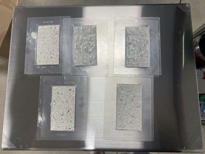
Figure 13. Bar molds filled with white-chocolate and cookie crumbs, on the vibration table for processing.
Uses for industrial vibration in food processing (partial list):
- Assist with accurate weighing
- Assist with mold release
- Assist with separation
- Break up clumps
- Cavitate
- Clean
- Disintegrate
- Disperse
- Emulsify
- Extract
- Homogenize
- Improve materials flow
- Move materials
- Remove bubbles from liquids
- Settle solids
- Spread or level ingredients
“All things are in a state of vibration. Vibrations from objects in our surroundings are constantly impinging upon us and carry to our senses a cognition of the external world”
–Max Heindel
The Oklahoma Cooperative Extension Service
WE ARE OKLAHOMA
The Cooperative Extension Service is the largest, most successful informal educational
organization in the world. It is a nationwide system funded and guided by a partnership
of federal, state, and local governments that delivers information to help people
help
themselves through the land-grant university system.
Extension carries out programs in the broad categories of agriculture, natural resources
and environment; family and consumer sciences; 4-H and other youth; and community
resource development. Extension staff members live and work among the people they
serve to help stimulate and educate Americans to plan ahead and cope with their problems.
Some characteristics of the Cooperative Extension system are:
- The federal, state, and local governments cooperatively share in its financial support and program direction.
- It is administered by the land-grant university as designated by the state legislature
through an
Extension director. - Extension programs are nonpolitical, objective, and research-based information.
- It provides practical, problem-oriented education for people of all ages. It is designated
to take
the knowledge of the university to those persons who do not or cannot participate in the formal
classroom instruction of the university. - It utilizes research from university, government, and other sources to help people make their own decisions.
- More than a million volunteers help multiply the impact of the Extension professional staff.
- It dispenses no funds to the public
- It is not a regulatory agency, but it does inform people of regulations and of their options in meeting them.
- Local programs are developed and carried out in full recognition of national problems and goals.
- The Extension staff educates people through personal contacts, meetings, demonstrations,
and the mass media. - Extension has the built-in flexibility to adjust its programs and subject matter to meet new needs. Activities shift from year to year as citizen groups and Extension workers close to the problems advise changes.