Bunker Planter Instructions
The Noble ‘Bunk’ planter uses two, erect standing semi-truck tires to form the planter frame. The planter measures approximately 8-feet in length, 40-inches wide and 20-inches deep. Dimensional lumber or sheet metal can be used to clad the structure. Based on early reviews, most folks prefer wood cladding over sheet metal. Due to its novel design, the bunk bed can be easily fitted with a low tunnel crop cover for extended season growing.
Bunker Planter Instructions
- Parts List
Total project price in 11/19 was $420.90.
- 2 - Truck tires 295/75R22.5 or 275/80R22.5*
- 14 - 2-inch x 4-inch x 8-foot pressure treated lumber
- 1 - 2-foot x 4-foot x 15/32-inch treated plywood
- 2 - 1-1/4-inch x 10-foot EMT steel tubing (14-gauge)
- 2 - 8-inch x 16-inch x 2-inch concrete paver (optional)
- 6 - Steel strap (24-inch)
- 8 - Nail plate (5-inch)
- 3, 1-lb boxes - Deck screws (3-inch)
- 1 Box (120 count) - Self tapping sheet metal screws (no.9 x 1-inch)
- 1 Box (35 count) - Self tapping sheet metal screws (no.10 x 1-1/2-inch)
- 1 Box (100 count) - Self tapping lath screws (no. 8 x ½-inch)
- 8 - Pipe hangers (1-1/4-inch EMT)
- 4 spray cans - ‘Flex Seal’ spray sealant
- 1 gallon - Wood Stain/sealant
- 15, 2-cu ft. bags** - Commercial nursery growing mix
*Tires should be the same size and have similar tread wear (same diameter)
** Volume of growing mix required dependent on amount of filler material used in bottom of bed - Tool Requirement
- Jig saw
- Cut off saw
- Impact driver
- Circular saw
- Plastic long tape
- Retractable tape measure
- Chalk line
- Garden rake
- Shovel
- Small sledge hammer
- Pipe driver
- Carpenter's square
- Torpedo level
- Carpenter's pencil
- Sharpie paint marker
- Large nail
- Carpenter's level: 4-foot
- Tire Preparation
Select two semi truck tires of identical size (same tread wear and diameter). Tires sharing the same circumference will have identical diameters. Recommended truck tire size: 295/75R22.5 or 275/80R22.5
Using a tape measure and a white marker, make four, evenly spaced vertical lines on both tires as shown. For ease of calculation, use a tape measure that measures in tenths of inches. Inserting a screw into the tire to hold the end of the tape measure frees up a hand for marking. A carpenter’s square or torpedo level can be used to ensure lines are plumb. If a torpedo level is used, make sure the tire is positioned on a level surface prior to marking. The four lines represent the top elevation, bottom elevation and midpoint elevation of the bed.
In order to accurately position tires on the ground posts, you will need to extend the white lines designating the top and bottom of the bed from the tread onto the sidewalls. Pick any set of lines opposite each other to serve as the top and bottom points. You can free-hand the mark or use a level or chalk line for increased accuracy.
- Site Preparation
Level a 4-foot by 10-foot area. Initial leveling can be done by eye. You may need to till the site in order to move the soil around. If the soil is tilled, plan on packing it following leveling in order to limit the amount of settling. You may need to install pavers (shown below) under the tires in order to prevent settling. A carpenter’s level used in conjunction with a jig (see section on jig construction) can be used to perform final leveling.
- Jig Utilization
When installing ground posts, use a jig to insure posts are installed accurately. Improperly placed ground posts will all but insure the bed will be out of square. Another advantage of using a jig is greater uniformity and consistency when installing multiple beds. If you anticipate installing multiple beds of your own or assisting a friend construct their own, the small investment spent on fabricating a jig will save you time and frustration. DIY jigs can be fabricated using square steel tubing or PVC pipe. Consider applying a weight on top of the jig to prevent it from moving during post insertion.
- Jig Construction: Steel Tubing
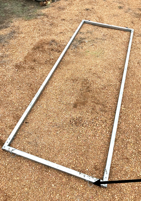
The jig pictured below is fabricated using 1-1/2-inch square tubing, angle braces, strap ties and pipe hangers. The dimensions given are recommended when using 295/75R22.5 or 275/80R22.5 truck tires and 2-inch x 4-inch x 8-foot lumber for planter construction.
- Jig Construction: PVC Tubing
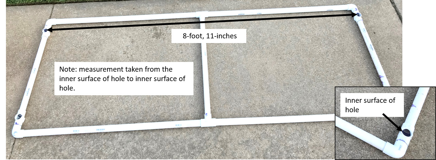
The jig pictured below is fabricated using 1-1/4-inch Sch 40 PVC pipe and assorted fittings. It is designed to be disassembled for portability. The dimensions given are recommended when using 295/75R22.5 or 275/80R22.5 truck tires and 2-inch x 4-inch x 8-foot lumber for planter construction.
To enable the jig to lay flat when in position, remove a set of opposite arms on each of the crosses prior to assembly. This is best accomplished using a cut-off saw. To make the job easier and safer, insert a piece of pipe into the fitting prior to sawing. Caution: Use eye protection when using power tools.
When fabricating the jig, cement the fittings to the cross members as shown. The side members need to be free to slip in and out of the fittings to assemble and disassemble the jig. To enable the side members to slip in and out of the fittings with the proper amount of resistance, you will need to slightly reduce the diameter of the pipe at both ends using sandpaper. Be careful not to remove too much as you do not want the frame to pull apart during use. Preferably, the side members should fit a little tight than too loose.
Check final jig measurements prior to use. The critical measurements include the distance between ground post holes at each end and between ends.
- Post Installation
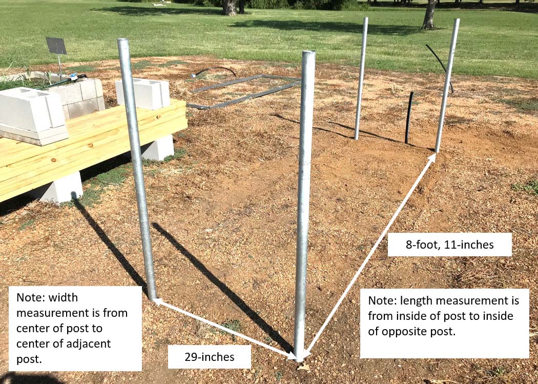
Using a cut-off saw, prepare four, 4-foot long posts using the 1-¼-inch EMT tubing. Insert posts into the jig and drive into the ground. To prevent flaring of ground posts when inserting, use a pipe driver or a driver made from a large bolt or hitch pin. Do not drive posts to their final depth at this time. Inserting them to a depth of 14 inches is sufficient at this stage. Use a torpedo level when driving posts to ensure they are installed plumb.
Once posts are securely in place the jig may be removed. The easiest method of removing the jig is to lift simultaneously from both ends. Lifting from one end causes the jig to bind against the posts greatly complicating the process. This is one activity where the use of two people is strongly encouraged.
Accurately placed ground posts made possible with use of a jig.
- Paver Installation
If you choose to install pavers to support the tires, center the pavers between the posts and offset by 1-1/2 inches as shown. Consider constructing a jig to simplify locating pavers.
Use an 8-foot section of angle iron, steel tubing or 2-inch x 4-inch board positioned as shown to ensure both pavers are level, one with the other. Make sure the pavers are well seated prior to checking the level. Standing on the pavers will help seat them. If you did a good job leveling the site prior to installing the pavers, only slight adjustments will be required during the installation process.
- Tire Attachment
If pavers have been installed, no additional leveling will be required. If pavers are not used, the elevation of one of the tires may need to be adjusted in order to ensure both are on the same level. Typically, if you did a good job leveling the site only a small adjustment will be required when leveling. All things being equal, it is easier to lower a tire by removing soil than it is to raise a tire by adding soil.
To accomplish leveling, the tires must be centered on the posts. Use a tape measure or a jig to locate the midpoint between both sets of posts and designate using a large nail.
Position the tires against the inner surface of the posts and center on the posts as shown making sure the bottom paint mark on the sidewall lines up with the nail. This technique is useful for centering tires when placed on the soil surface or on pavers.
Use the white marks at the top of the tires as a point of reference to assist with centering. A 2-inch x 4-inch x 4-foot board can be used as a temporary brace to keep the tires pinned against the posts to ensure they stay centered.
Position an 8-foot section of angle iron, steel tubing or 2-inch x 4-inch board as shown to check the level. Make elevation adjustments to one of the tires as needed.
With the leveling process completed (and tires centered on posts), drive posts to their final depth. When driven to the proper depth the top of each post should be even with the tread at its closet point. The posts should not protrude above the tread. A 4-foot carpenter’s level can be used to ensure the post tops are level one with the other.
The tire will be centered on the posts if the distance from the top paint mark to both posts is the same. This assumes the location of the paint mark is accurate and the posts are installed plumb. With the tire centered on the posts, attach using pipe hangers and 1-1/2-inch sheet metal screws as shown. Position pipe hangers at the same location on each post before fastening.
- Siding Installation
As mentioned in the introduction, several material options are available to construct the sides of the planter. This section details the use of 2-inch x 4-inch x 8-foot treated lumber to construct the planter. When selecting boards, avoid bent or misshapen ones. The use of straight boards makes assembly easier and creates a better looking bed. Also, most lumber is not cut precisely to length at the mill, so be sure and measure each board and cut to size prior to fastening.
Starting on one side of the planter, locate the midpoint paint mark on both tires. Attach a support block to one of the tires as shown using 3-inch deck screws.
Before attaching, partially insert 3-inch deck screws on each end of the boards. To ensure a tight, uniform connection, use a minimum of two screws and position screws on a diagonal as shown. Partially inserting screws into the boards makes attachment much easier.
With a board centered on the tires and one end resting on the support block (or held in place by an extra set of hands), align the bottom of the board at the opposite end with the paint mark on the tire. Before attaching, check the level using a 4-foot level. In the event the board location as determined by the paint mark and the carpenter’s level do not agree, go with the location as determined by the level. You will need to apply pressure to the board while inserting the screws to insure a tight fit.
Continue to attach boards to the tire frame as shown. Using two people makes the process go much quicker. A total of seven boards are required to complete each side of the planter.
In order to access lower boards using an impact driver, plan on removing soil from around the base of the tire as shown.
If you plan on equipping your planter with a crop cover, now is the best time to install the hoop receptacles. Using a chop saw, cut six, 3-1/2-inch hoop receptacles using the 1-inch EMT tubing. Use a file to remove burrs (See Bunk Planter Crop Cover parts list).
Attach receptacles to the bunk bed using pipe hangers and 1-inch sheet metal screws. Position the lower pipe hanger close to the bottom edge of the receptacle.
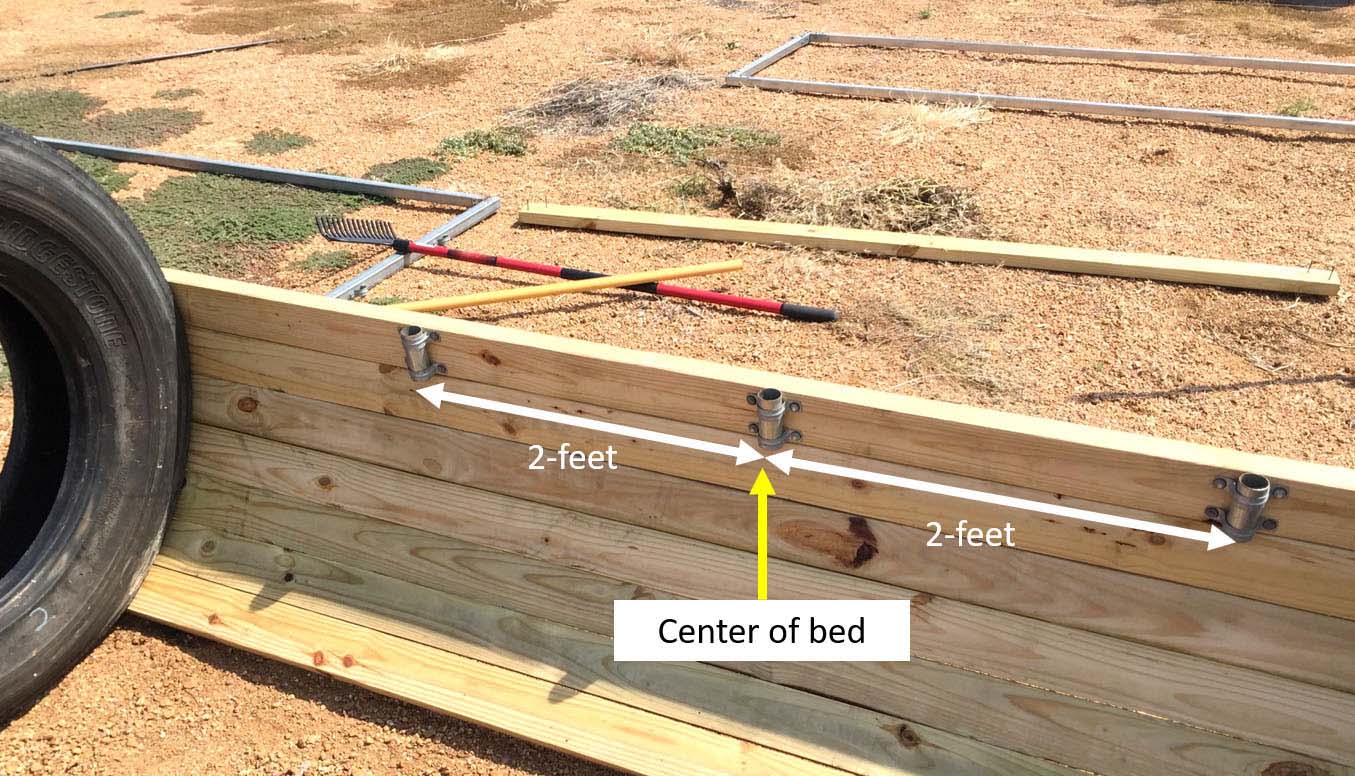
Evenly space receptacles along the inner surface of each side as shown.
Install 24-inch long steel straps to strengthen the bed sides. Use 1-inch sheet metal screws to attach the strapping.
Plan on installing three straps on each side. Locate straps next to the hoop receptacles.
Jump to the opposite side of the planter and repeat the process. Use the paint mark on the tire as the starting point. Before installing the first board, place a 4-foot level across the top of the planter (one side to the other) to ensure the board is installed level. Complete installation of remaining boards, hoop receptacles and steel straps.
- End Cap InstallationUse a jig saw to cut two disks from a 15/32-inch piece of pressure treated plywood. The disks should measure 23-1/4-inches in diameter, large enough to overlap the 22-inch wheel diameter. Attach the disks to the interior surface of tires as shown using 5-inch nail plates, 1-inch sheet metal screws and ½-inch lath screws.
- Sealant ApplicationTo increase the service life of the planter, apply Flex Seal to the inner surface of the planter and to the end caps to create a water barrier. Apply a combination stain/sealer to all exterior wood surfaces.
- Add Growing MediumTo decease the volume of soil/growing mix required, consider filling the bottom half of the planter with shredded tree trimmings, bricks, etc.
Bunker Planter Crop Cover - Assemble & Installation Plans
- Bunker Planter Crop Cover Parts List
Total cost was $158.60 in November 2019.
- 2 - Greenhouse poly film (6-mil clear) 4-foot X 9-foot
- 1 - EMT steel tubing (1-inch X 10-foot)
- 4 - EMT steel tubing (3/4-inch X 10-foot)
- 2 - Bungee cord (4-foot)
- 1 - 24 inch Horizontal Plastic Closure Strips for corrugated roofing (6 Pack)
- 1 - Eye screws (#106 X 1-13/16-inch) 2-pack
- 1 - PVC snap clamps (1/2-inch X 48-inch)* 10-pack
- 1 Box (120 count) - Self tapping sheet metal screws (no.9 X 1-inch)
- 1 Box (30 count) - Deck (wood) screws (no.8 X 1-1/4-inch)
- 1 Roll - ADS 100-PSI Poly Coil Pipe (3/4-inch x 100-foot)
- 1 Roll - White Braided Nylon Rope (3/16-inch x 50-foot)
- 12 - Pipe hangers (1-inch EMT)
- 1 Box (50 count) - Hex drive Tek screws (no.10 X ¾-inch)
- 4 - Pipe hangers (1/2-inch EMT)
- 4 - Plastic barbed tee fitting (3/4-inch)
- 2 joints - Rebar (3/8-inch x 10-foot)
Note: Clamp size that fits ½-inch sch 40 PVC pipe is recommended for use on ¾-inch EMT steel conduit.
- Instructions
Insert a single ¾-inch Tek screw into the base of each hoop receptacle as shown. The screw serves as a stop for the hoop when inserted into the receptacle.
Prepare hoops. Cut three pieces of tubing from the roll of ¾-inch poly pipe. Each piece should measure approximately 61 inches.
Insert hoops into the receptacles and check for fit. Use a joint of the ¾-inch conduit to ensure the hoops match the height of the tires. If a hoop is too long, cut down to fit; if too short, cut another piece to fit.
Attach plastic closure strips to each tire. The slots in the strips prevent the cover from sliding on the frame. The closure strips shown in the photo come in 24-inch sections that snap together. Connect two sections together, center on the tire as shown and secure using 1-1/4-inch deck screws. Note: the use of closure strips is optional. Being diligent in keeping the bungee cords and straps tight will reduce sliding. The choice is yours.
Install eyes screws. The eye screws work in combination with the rope to restrain the cover at the center of the planter. Install one screw in the fourth board from the top and at the center of the planter. Install the other eye screw in the top board on the opposite side and in the center of the planter.
Attach a ½-inch pipe hanger to both sides of each tire as shown using 1-inch sheet metal screws. The pipe hangers are used to attach the bungee cords to the frame.
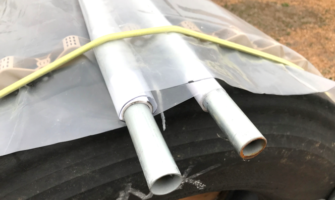
Assemble the planter cover. The cover consists of two sections. Each section is composed of two pipe reels, a 4-foot x 9-foot piece of greenhouse poly film and 20 snap clamps.
Fabricate the reels. Using a chop saw, cut each ¾-inch conduit to a length of 9-1/2-feet. Use a file to remove burrs.
Prepare two, 4-foot by 9-foot pieces of poly film. A large work table makes a great surface to measure and cut the film to size.
Use a chop saw to cut the snap clamp strip into individual clamps measuring 1-1/2-inch.
Designate snap clamp location on the pipe reels. Using a permanent marker, make a mark on each reel three inches from both ends and on one-foot centers between the outer marks.
Move one of the poly film pieces to the edge of the table. Orient a pipe reel along one of the long edges as shown. The end mark on the reel should be aligned with the edge of the poly film. Starting at one end, roll the edge of the film around the reel until it contacts the film. Attach the film to the reel as shown using a snap clamp.
Repeat process on each reel until both pieces of poly film are attached. With both edges of the poly film attached, roll up the cover from both sides evenly distributing the plastic on both reels.
Install bungee cords. Place each section of the cover under the bungees and on the closure strips as shown. The cover can be installed two ways; with the film rolled over the top of the reels or under the reels.
Standing on one side of the bed, grab the top reel with both hands and slowly unroll the poly film moving the reel upward one section on the closure strips at a time. Continue unrolling the film until you reach the first valley past the paint mark (top of bed). While unrolling the film, keep tension on the reel to maintain a tight roll. The tension provided by the bungee cords will prevent excess unreeling of the film. Next, unroll the poly film on the bottom reel using the same basic procedure until the reel comes to rest on the side of the planter. Move to the opposite side of the bed and repeat procedure with the second cover section. To create a rain proof seal, the top reel of the second section must overlap the top reel of the first section as shown.
Caption: Cover installed with the film rolled over the top of the reel. Notice how one section of the cover overlaps the other to create a water tight seal.
To more fully secure cover and limit flapping of the poly film, install a rope strap. Secure the strap to the frame using the previously installed eye screws. Tie a loop in one end of a 14-foot long section of rope. Run the other end through both eye screws and over the top of the cover. Position the rope on either side of the center hoop. Tie off the free end by running it through the loop and securing with a half hitch. To increase tension on the cover, loosen the knot, pull down on the rope and tie off with a half hitch.
During high wind conditions the poly film has a tendency to unwind on the reels resulting in a loose fitting cover. To prevent the reels from turning, install ‘tee’ handles on one end of each reel. A 3/8-inch rebar stake placed through the handle effectively locks the reels in place. A ¾-inch plastic barbed tee fitting makes a great handle. In order for the fitting to slip inside the pipe reel the diameter of the perpendicular arm will need to be reduced. Use a grinder to remove just enough plastic to achieve a secure fit.
With the cover in the closed position and with as much slack in the poly film removed as possible, install two tees to reels on one end of the bed as shown and two tees to reels at the opposite end as shown. Install the tees in an upright position on the reels as shown.
Secure the tees to the reels using ¾-inch Tek screws.
Using a chop saw, cut four pieces of 3/8-inch rebar long enough to protrude above the tee handles when installed. Bend each rebar as shown to create a handle.
To vent the crop cover, remove stakes, move reels to the desired position and reinstall stakes.

